Liquid Cooling PC


flowchart TB
subgraph a[Motherboard];
direction LR
a1[USB 2 Connector];
end;
subgraph b[Water Loop];
direction TB
b1[iCue Commander Pro]
b2[RGB Hub]
b3[TT Hub]
b4[Fans]
b5[Radiator]
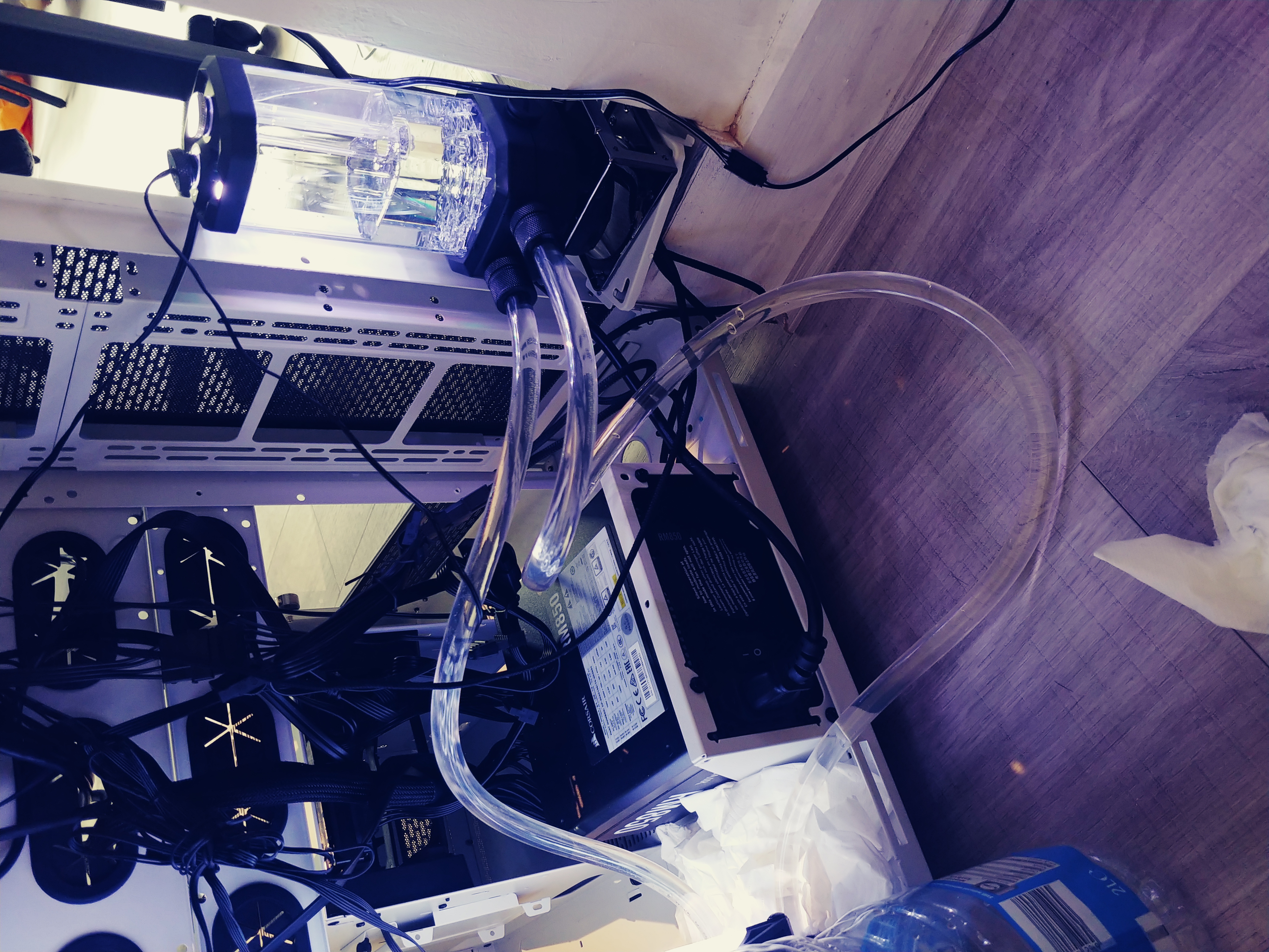
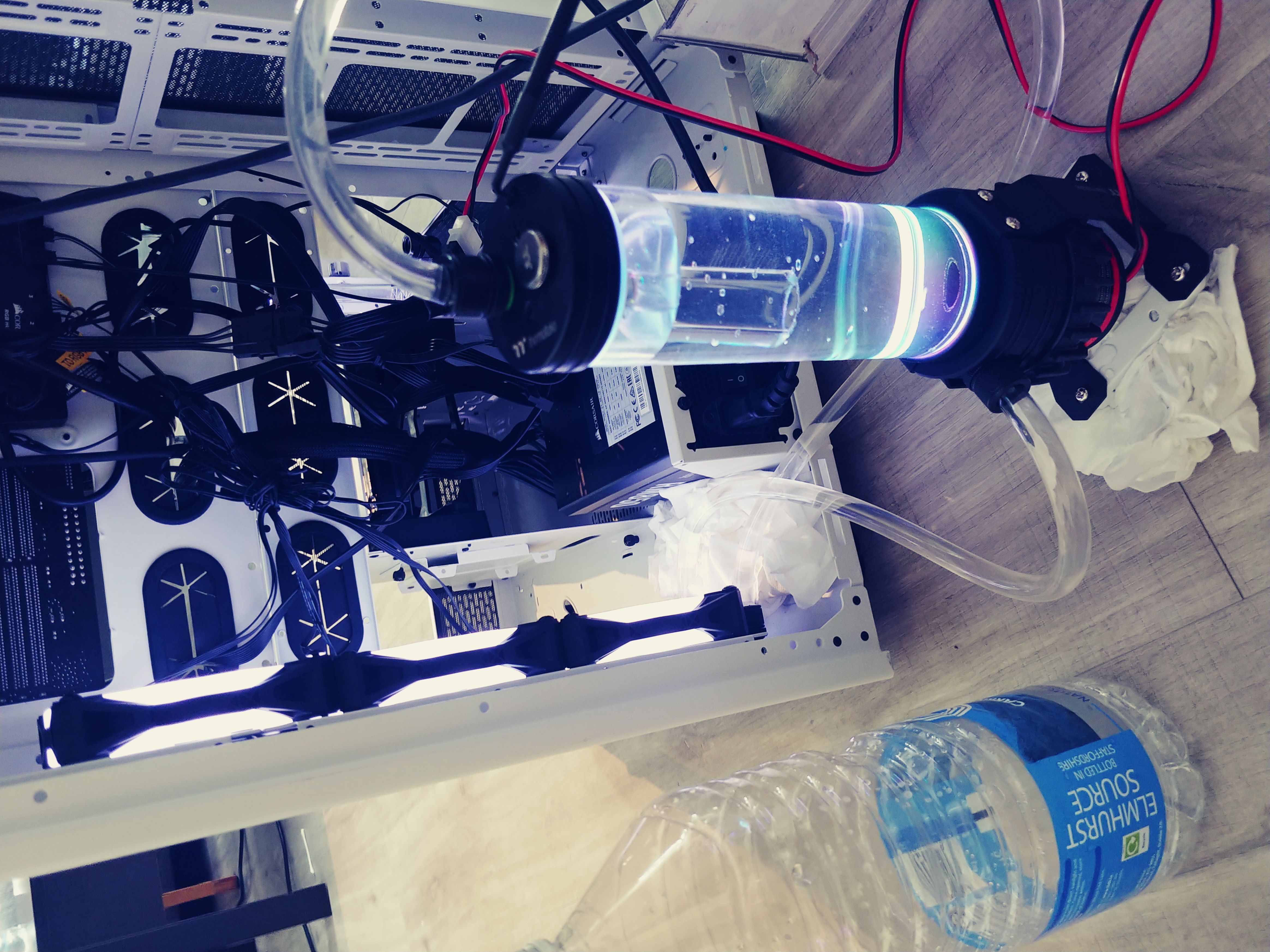
b6[TT Pump]
b7[Corsair Pump]
b8[XC7 CPU Block]
b9[XG7 GPU Block]
b4 -->|Mount| b5;
end;
subgraph c[RM 850];
c1[SATA];
c2[MOLEX]
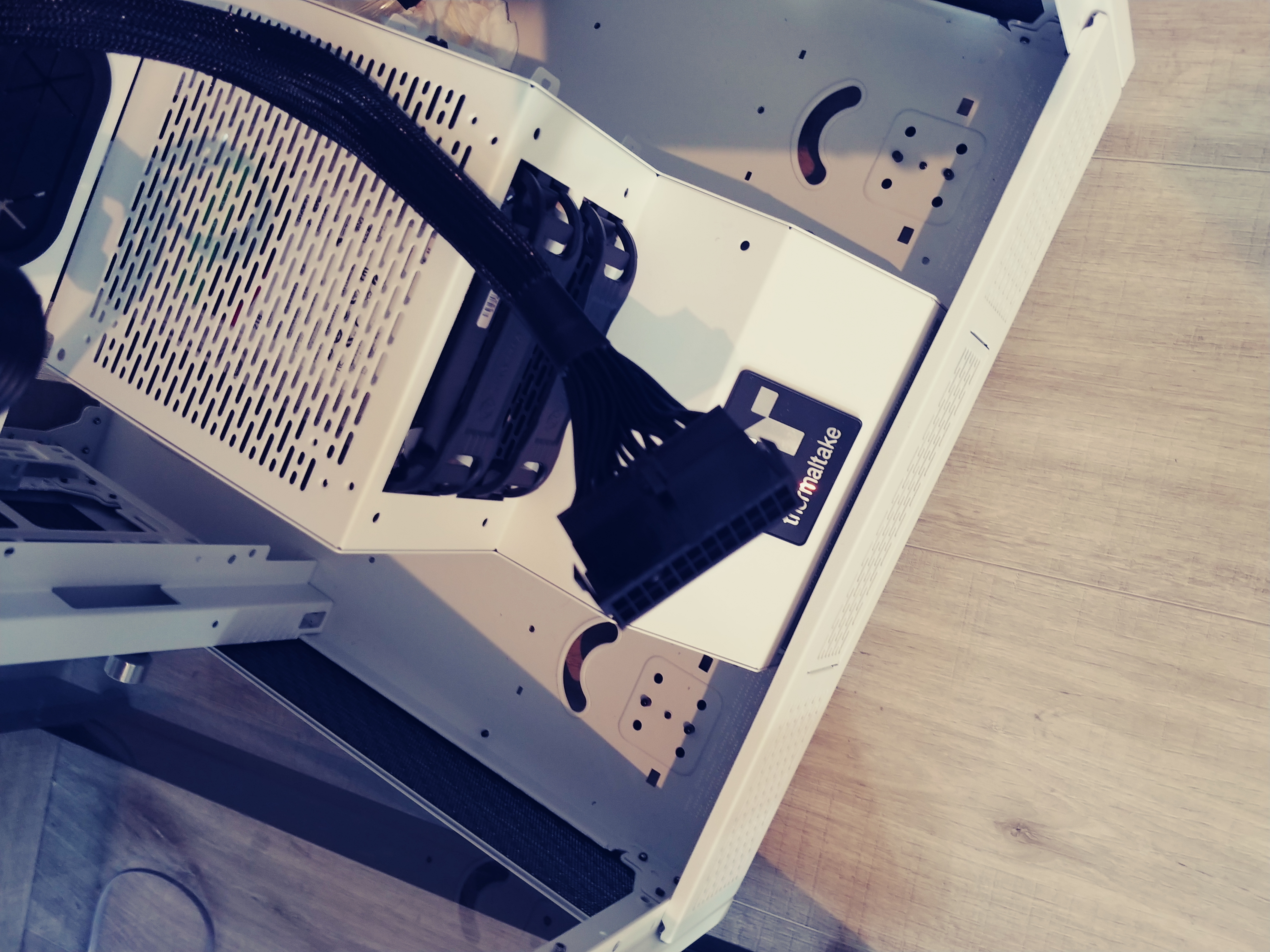
c3[ATX 24 pin connector]
end;
b1 --> a1;
b1 -->|LED| b2;
b1 -->|USB| b3;
b7 -->|Fan, LED, TEMP| b1;
b7 --> c2;
b6 --> c2;
b6 -->|USB| b3;
b3 --> c2;
b4 -->|LED| b2;
b4 -->|Fan| b1;
b7 -..->|tube| b9;
b9 -..->|tube| b8;
b8 -..->|tube| b5;
b5 -..->|tube| b6;
b6 -..->|tube| b7;
b1 --> c1;
b2 --> c1;
b8 -->|daisy chain| b9;
b9 -->|daisy chain| b7;
c3 --> d[reset cap];